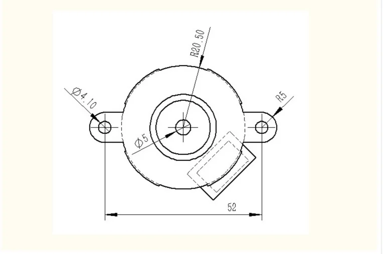
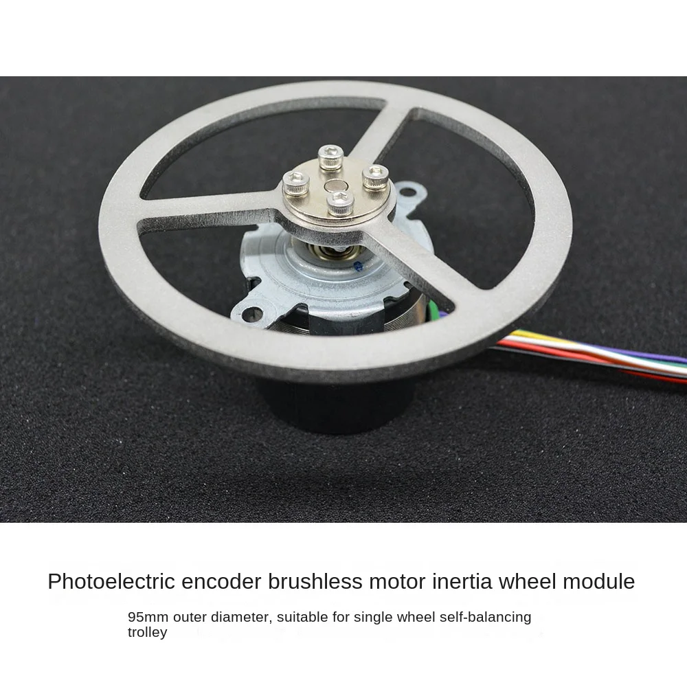
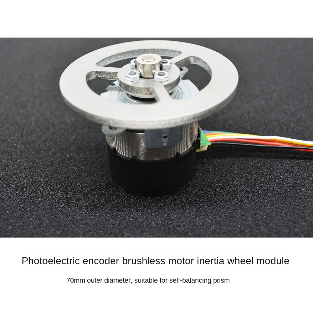
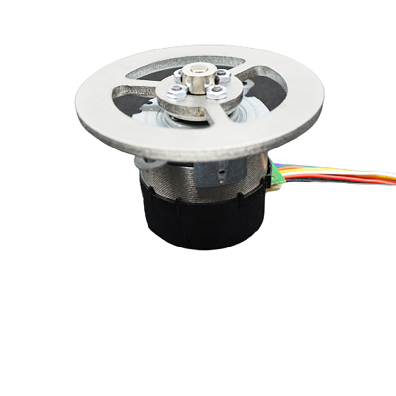
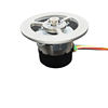
70mm/95mm Photoelectric Encoder With 12V Brushless Motor Inertia Flywheel Module for STM32 Robot Balance Robot Car Motor DIY Kit
[Please read carefully before buying]
Title: Inertia wheel assembly flywheel module balancing car
.High power encoder brushless motor High power encoder brushless motor, important things to say three times, brushless built-in drive! Brushless built-in drive! Brushless built-in drive! Why so much emphasis on brushless built-in drive? The brushless motor eliminates the noise of mechanical commutation of the brush motor, extends the service life of the motor, built-in drive, we do not use TB6612, L298N these drive modules, simplify our wiring!
Note:
1, the printer disassembly machine, but each one has passed our factory testing, including the speed test, encoder output test, all indicators are normal, we attach the quality inspection label for delivery!
2, this motor is not like the DC motor to connect the battery and turn, you need to have a certain electronic technology foundation and practical ability of the students to use! Students who have no hands-on ability may not be able to play! Before, some students often said that there was a problem with the motor to return, but we got the test is normal!
3, we strongly recommend that you directly buy our shop car or triangular prism finished products, because too many students waste too much time on this, parameter debugging is difficult, no reference to a finished product is very difficult to tune! Many students just buy a momentum wheel module at the beginning, and after a month or two, they directly buy the whole car or triangular prism.
Parameter description:
Encoder Type 100-wire photoelectric orthogonal encoder
Rated torque locked torque 3.85N.cm4N.cm
Rated current control mode 0.5APWM(low level effective)
Motor weight 130g
Gridlock current 1A
Rated voltage 12-24V
Rated power 10W
Maximum speed 3000rpm(12V)
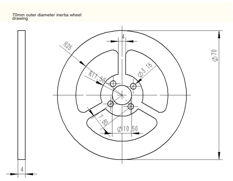
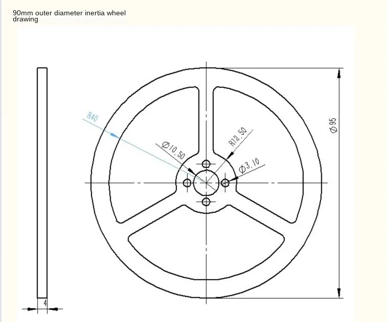
Moment of inertia 0.00006kg*m2(7cm diameter)0.0001kg*m2(95mm diameter)
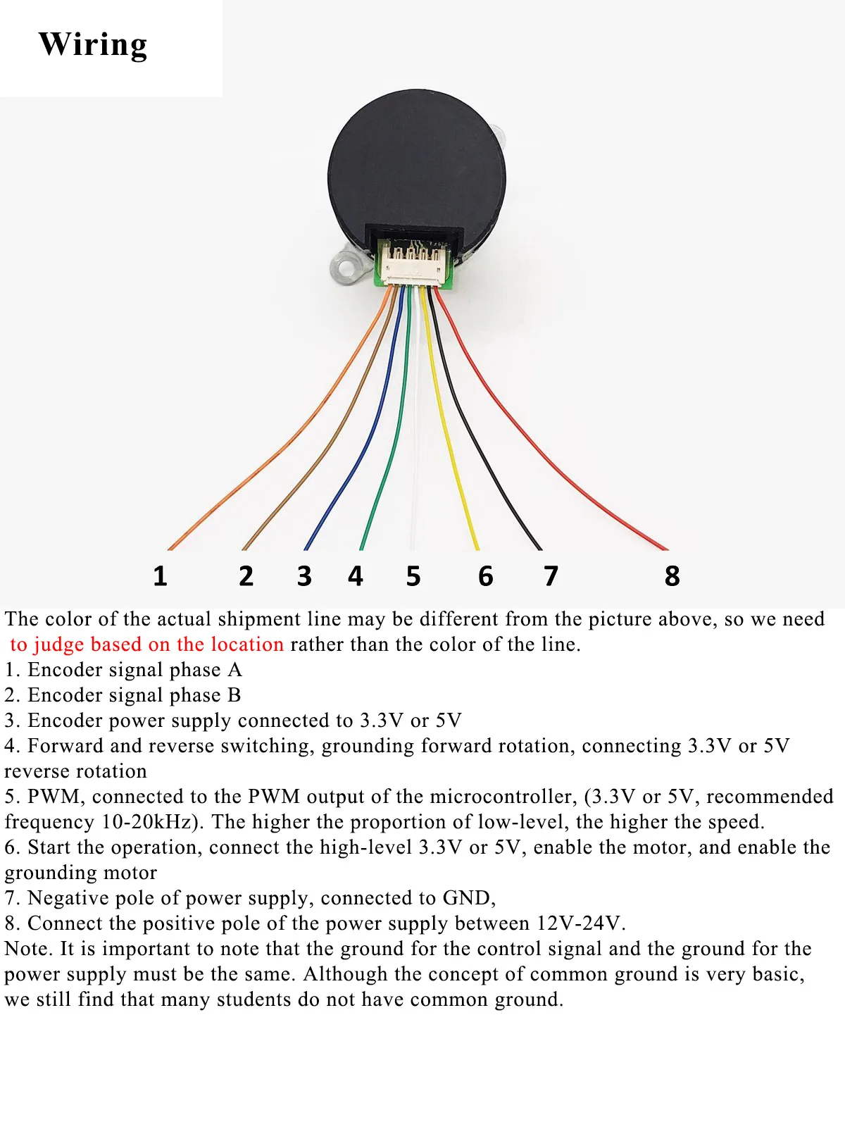
The actual shipped line color may be different from the figure above, we should judge according to the position rather than the color of the line.
1. Encoder signal phase A;
2. Encoder signal B phase;
3. Encoder power supply is connected to 3.3V or 5V;
4. positive and negative switching, grounding, 3.3V or 5v reverse;
5. PWM, PWM output of MCU (3.3V or 5V, recommended frequency 1020kHz), the higher the proportion of low level, the higher the speed.
6. start running, connect high level 3.3V or 5V, motor enable, grounding motor disabled;
7. The negative electrode of the power supply is connected to GND;
8. Connect the positive terminal of the power supply between 12V and 24V. It must be noted that the control signal and the power supply must be one place. Although the concept of common ground is very basic, we still found that many students do not have common ground!
Shipping list :
1. Inertia wheel
2. Flange coupling *1
3. Encoder brushless motor *1
4. L-shaped hex wrench *1
5. Kimi screws *2
6. Screwdriver *1
7. M4 screws *2
8. M4 nuts *2
9, motor wiring *2
