Wiki:Datasheet
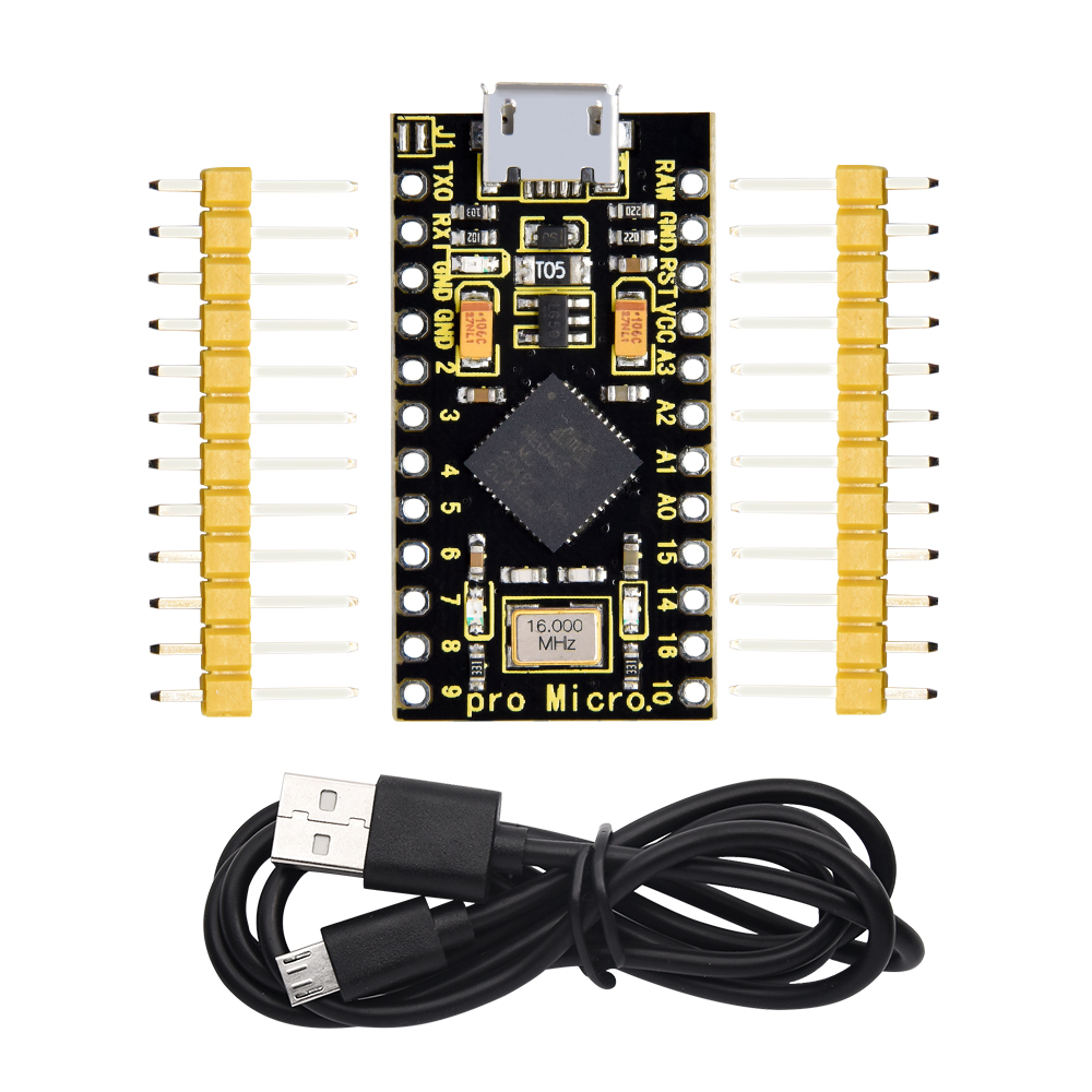
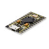
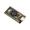
The processor core of Keyestudio PRO MICRO development board is ATMEGA32U4-MU, fully compatible with ARDUINO.
It contains everything needed to support the microcontroller; simply connect it to a computer with a USB cable to get started.
It has 18 digital input/output pins (of which 5 can be used as PWM output), 9 analog input, a 16 MHz crystal oscillator and a micro USB port.
In addition, its working voltage is 5V and we can supply power via micro USB cable and port RAW GND (DC 7-9V).
It is easy to integrate this Micro in everyday objects to make them interactive.
To facilitate the physical design, the board is not welded with pin headers, so you can solder the pin headers by yourself. And the package includes 2pcs of yellow 1*12 2.54 straight pins and 1m black micro USB cable.
Specification
Microcontroller: ATMEGA32U4-MU
RAW: DC 7-9V
VCC: 5V at 500mA
Digital I/O Pins:18 (of which 5 provide PWM output)
Analog Input Pins:9
Maximum current for chip: 200mA
Maximum current per pin: 40mA
Recommended current per pin: 20mA
8-bit Atmel AVR
Flash Program Memory: 32kB
EEPROM: 1kB
Internal SRAM 2.5kB
ADC:10-bit
PWM:8bit


Specialized Functions of Some Pins:
-
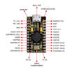
Digital Port:RX(D0), TX(D1), D2-D10, D14-D16 and A0-A3(D18-D21)
-
Analog Port:A0-A3, D4(A6), D6(A7), D8(A8), D9(A9)and D10(A10)
-
PWM Port (Pulse-Width Modulation)::D3、D5、D6、D9、D10
-
External interrupt: D3(interrupt 0), D2(interrupt 1), D0(interrupt 2), D1(interrupt 3) and D7(interrupt 4)
-
Serial Communication Port:RX (D0) ,TX (D1)
-
SPI Communication Port:D14 (MISO), D15 (SCLK) and D16 (MOSI)
-
I2C Communication Port:D2 (SDA) and D3(SCL)
-
RAW:external power DC 7-9V

